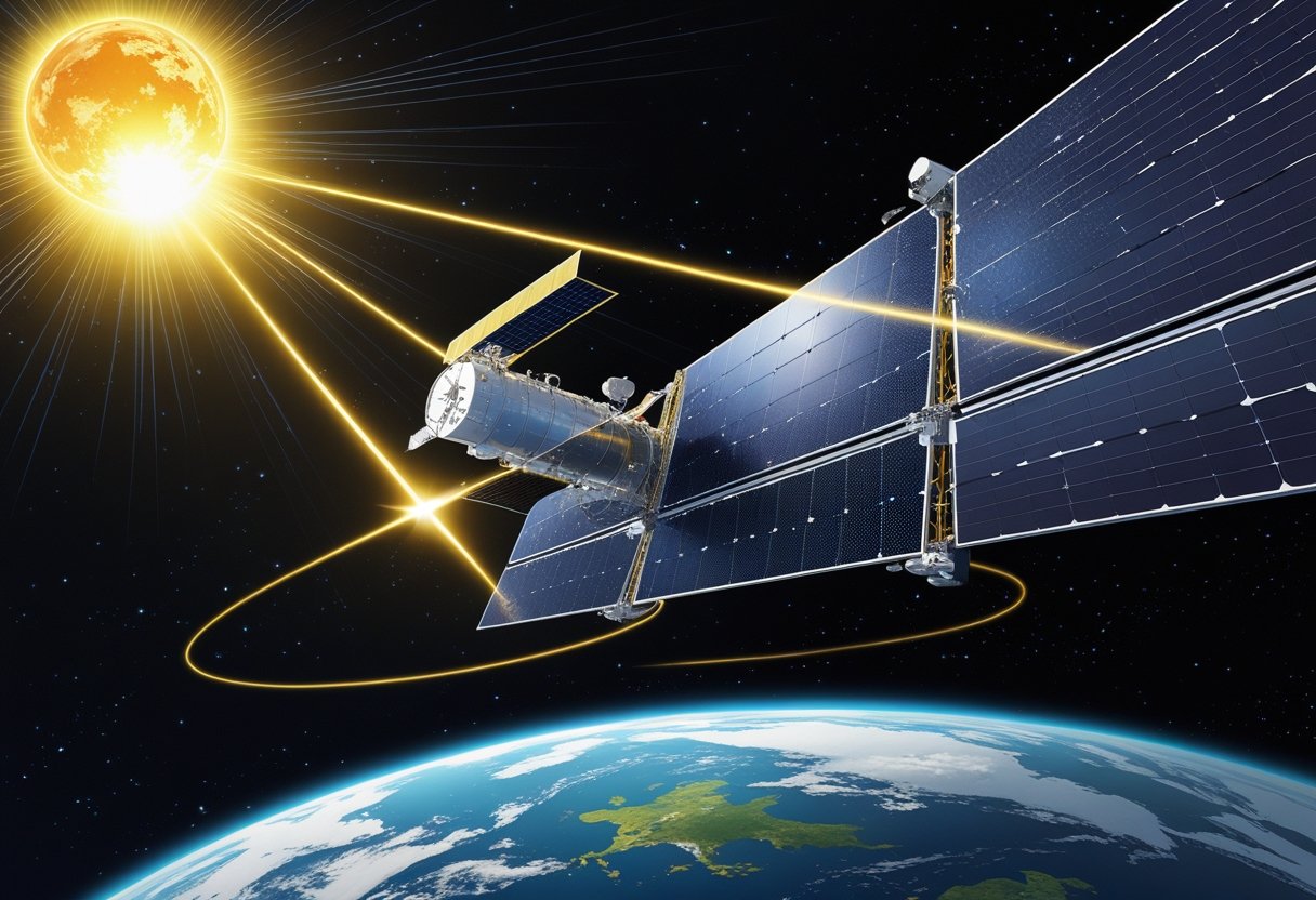
You tap sunlight in empty space the same way solar panels do on Earth, but without atmosphere or nightfall the panels deliver more continuous, efficient power for satellites, stations, and probes. Solar arrays convert sunlight into electricity through photovoltaic cells, then power onboard systems or beam energy toward Earth for long-term missions.

You’ll explore how panels work, how engineers design lightweight, radiation-tolerant arrays, and how concepts like space-based solar power could change terrestrial grids. Expect clear explanations of performance advantages, orbital choices that matter, and the technical challenges that still need solving.
Fundamentals of Solar Panels in Space
You’ll learn how sunlight becomes electrical power at the cell level, why space changes panel design and performance, and how the intensity and spectrum of sunlight set the limits on output.
The Photovoltaic Effect and Solar Cells
Photovoltaic cells convert photons into electrical current inside a semiconductor junction. When light hits a p–n junction, photons with energy above the bandgap free electrons and holes; an internal electric field separates them and produces a voltage you can draw current from.
Space-grade cells typically use monocrystalline silicon or gallium arsenide (GaAs). GaAs offers higher efficiency and radiation tolerance; silicon is cheaper but bulkier for the same power. Cells are wired in series-parallel to reach required bus voltages and currents for your spacecraft electronics.
Important cell parameters you should watch: open-circuit voltage (Voc), short-circuit current (Isc), and maximum power point (Pmax). Space manufacturing adds anti-reflective coatings, coverglass, and edge seals to protect cells from micrometeoroids, atomic oxygen, and radiation while keeping mass low.
Differences from Terrestrial Solar Panels
In space you avoid clouds, atmosphere, and nighttime losses, so your panels can deliver higher average irradiance per unit area. That advantage comes with new constraints: vacuum thermal cycling, ionizing radiation, and launch vibration.
You must design for long-term degradation from proton and electron flux; expect a few percent output loss per year depending on orbit. Thermal control becomes active: without convection you rely on conduction and radiation to dump heat, so substrates and adhesives must match thermal expansion to prevent cell cracking.
Mechanical design favors deployable arrays or articulated wings to maximize sun-pointing. You’ll see lightweight composites, thin glass covers, and hinge mechanisms that terrestrial rooftop panels don’t need. Redundancy and fault-tolerant stringing protect your mission against single-cell failures.
The Solar Spectrum and Solar Constant
At Earth’s distance, sunlight at 1 astronomical unit (1 AU) delivers about 1,361 W/m² outside the atmosphere — the solar constant that sets the upper bound for photovoltaic power. In low Earth orbit you get this full spectral irradiance when unobstructed, so your peak output uses near-sunlight levels.
The spectrum in space is richer in ultraviolet and has less atmospheric absorption, so cell spectral response matters: cells with higher bandgaps capture more visible/UV efficiently, while lower-bandgap materials harvest infrared better. You should match cell bandgap to the in-space spectrum to optimize efficiency.
Intensity falls with the inverse square of distance; beyond Mars you must increase array area or switch to alternative power like RTGs. Also consider spectral shifts during solar activity and wavelength-dependent radiation damage, which change cell performance over mission life.
Design and Engineering of Space Solar Arrays
You’ll learn which materials and cell types deliver the best watts per kilogram, how engineers control temperature and radiation damage, and the mechanical systems that stow and point arrays for consistent power.
Space-Grade Materials and Multi-Junction Cells
You rely on cells that keep producing under vacuum and temperature extremes. Multi-junction photovoltaic cells stack distinct semiconductor layers to harvest different portions of the solar spectrum, so a GaAs/InGaP/Ge triple-junction cell converts more sunlight to electricity than single-junction silicon for the same area. These cells give higher efficiency and better low-irradiance performance, which reduces array area and mass for a given power budget.
Materials for substrates and interconnects must resist atomic oxygen, thermal cycling, and mechanical stress. Flexible thin-film solar cells can save stowed volume and mass, but you trade some efficiency and require careful adhesion and encapsulation to prevent micrometeoroid punctures. Conductive wiring uses silver or copper with redundant paths, and adhesives/films are chosen for low outgassing.
Thermal Management and Radiation Protection
You must keep cells within their operating temperature range to maintain efficiency and lifetime. Passive thermal control uses white or low-emissivity coatings, thermal blankets, and radiators sized to reject waste heat. Active methods include heat pipes embedded in substrates to spread hot spots and temperature sensors tied to power electronics that throttle output if cells overheat.
Radiation degrades photovoltaic performance over time. You mitigate this with radiation-tolerant cell chemistries (e.g., GaAs), shielding layers where mass allows, and cell-string redundancy so damaged strings can be isolated. Mission planners model cumulative displacement damage and total ionizing dose to predict end-of-life power and set initial overcapacity margins.
Structural Deployment and Sun-Tracking
You need compact stowage and reliable deployment mechanisms to turn small fairing volume into large collection area. Roll-out blankets, Z-folded wings, and fan-fold architectures balance packing density, mass-to-power ratio, and deployment complexity. Mechanisms use spring- or motor-driven booms, latch systems, and measured release sequences to avoid snagging.
Once deployed, active sun-tracking increases average power. Single- or dual-axis trackers orient the array normal to the sun to maximize incident irradiance across the solar spectrum. Your attitude control system integrates array torque management and motorized drives with position encoders to limit flexing and oscillation that would reduce power or induce structural fatigue.
Space-Based Solar Power: Concept and Operation
You’ll learn how orbital collectors gather sunlight continuously, convert it to a beam, and deliver usable electricity to ground sites via large receiving antennas. The explanation covers why space solar outperforms terrestrial panels, how the beam is formed and steered, and what a rectenna does to turn beamed energy into grid power.
Continuous Solar Energy Collection in Orbit
In orbit, solar power satellites (SPS) avoid atmospheric attenuation and regular cloud cover, so your collectors can harvest sunlight nearly 24/7 when placed in geostationary or high-altitude orbits. You’ll see higher incident irradiance because there’s no scattering or absorption; typical orbit designs target GEO for persistent line-of-sight to a fixed ground receiver.
Array design matters: ultralight, foldable photovoltaic or concentrated PV panels maximize watts per kilogram. Thermal control and radiation hardening keep your cells efficient over years. Modular assembly and on-orbit servicing let you scale capacity while replacing degraded modules.
Power management systems on the spacecraft convert array output to stable DC, then to the beam format (microwave or laser). Pointing accuracy and attitude control keep the collectors and converters aligned with the Sun and the ground transmission aperture.
Wireless Power Transmission Methods
You’ll choose between microwave and laser power beaming based on range, efficiency, and safety constraints. Microwave transmission typically uses gigahertz-range frequencies (commonly proposed ~2.45 GHz or ~5.8 GHz) because they penetrate atmosphere well and allow efficient rectification at the ground receiver.
Lasers concentrate energy into narrow optical beams, reducing aperture size but increasing atmospheric sensitivity—clouds, aerosols, and turbulence can degrade transmission. Lasers can achieve higher energy density and potentially smaller receivers, but require adaptive optics and safety exclusion zones.
Onboard conversion stages: DC → RF or optical emitter → beam-forming phased arrays or optical beam directors. Beam steering uses phased-array phase control for microwaves or deformable mirrors and tracking for lasers. You’ll monitor beam shape, power density, and downlink path to meet regulatory and safety limits while maximizing transfer efficiency.
Receiving Antennas (Rectennas) on Earth
Rectennas convert microwave beams to DC using arrays of receiving elements and rectifying diodes; you’ll place them in open, low-population sites to manage power density and safety. A typical rectenna is a large, low-profile array of dipole or patch elements with integrated Schottky diodes to achieve conversion efficiencies often modeled above 80% under ideal alignment.
Layout and land use: rectennas can cover square kilometers for multi-gigawatt links, but they can also be modular and distributed. You’ll integrate power conditioning, transformers, and grid interconnection equipment at the rectenna site to deliver stable AC power.
For laser-based links, ground receivers use photovoltaic converters or thermal receivers. Those installations require tracking, cooling, and more stringent atmospheric-clearance planning. In both cases, you must coordinate siting, electromagnetic safety limits, and grid acceptance to turn beamed energy into reliable electricity.
Relevant technical reading includes overviews of space-based solar power and NASA’s explanation of collecting and transmitting orbital solar energy via microwaves or lasers.
Advantages of Solar Energy in Space
Space-based solar systems deliver higher sunlight intensity, steady output, and the possibility of supplying large, continuous clean energy. You’ll see gains in conversion efficiency, predictable operations unaffected by weather, and potential to feed grids with baseload renewable power.
Higher Efficiency and Reliability
You get more sunlight in space: sunlight at Earth orbit is about 1,366 W/m² with no atmospheric scattering or absorption. That raises raw irradiance compared with ground-level values and lets high-efficiency cells—like multijunction GaAs—operate closer to their rated performance. Those cells routinely reach 30–40% or higher in laboratory and deployed space settings, so for each square meter you capture more usable energy than typical terrestrial panels.
Reliability improves because thermal cycling and soiling are different in orbit. You won’t deal with dust, pollen, or corrosion that reduce output on Earth, though you must design for radiation damage and micrometeoroid impacts. You’ll also use redundant strings and degradation-management strategies so arrays maintain steady output over decades, supporting mission-critical loads and long-duration remote operations.
Weather and Day-Night Independence
In space, you escape clouds, atmospheric water vapor, and night cycles that interrupt terrestrial solar generation. That means continuous or near-continuous power when arrays remain sun-facing, which reduces or eliminates the scale of battery storage you need on the ground for firm capacity. For Sun-synchronous or geostationary placements you can plan predictable daily and seasonal profiles with minimal short-term variability.
You’ll still face eclipse periods for some orbits, and atmospheric transmission matters if you beam power to Earth, but system-level architectures (arrays, storage, ground receivers) let you manage that reliably. Minimizing weather-caused variability improves grid integration and reduces curtailment of other renewables, making solar energy in space a robust complement to terrestrial renewables.
Potential for Global Clean Energy Supply
Space solar panels open the possibility of continuous clean energy that can support large-scale demand centers. With orbital collection, you can concentrate generation where sunlight is strongest year-round and transmit power to distant loads using microwave or laser links. That capability could let you deliver renewable energy to regions with poor solar resources, remote military or research bases, and disaster relief operations.
You’ll need rectennas or optical receivers on the ground and careful regulatory and safety systems, but the arithmetic scales: multi-megawatt to gigawatt orbital stations can provide baseload clean energy without combustion emissions. If you pursue this route, the biggest practical constraints are launch cost, in-orbit assembly, and sustained operations—not the physical availability of solar energy itself.
Relevant further reading explains technical pathways and demonstrations for these capabilities, including power-beaming and orbital assembly developments described in recent technical reviews and program reports: Space-Based Solar Power 2026: Advancements Driving Continuous Clean ….
Key Orbits, Missions, and Milestones
Space solar power has practical trade-offs across orbits, early demonstrations, and heavy-lift launch systems that change how you plan panels, transmission, and assembly.
Geostationary vs. Low Earth Orbit
In geostationary orbit (GEO) a satellite stays fixed over one point on Earth at ~35,786 km altitude. That stability simplifies continuous power beaming and fixed ground receiver (rectenna) alignment. GEO favors large, high-output arrays and is the most discussed location for commercial space solar power because it gives you nearly uninterrupted sunlight and a constant transmission geometry.
Low Earth orbit (LEO) sits roughly 200–2,000 km above Earth and offers lower launch and deployment cost per kilogram. You’ll trade continuous sunlight for frequent orbital shadowing and Doppler-shifted transmission links. LEO suits modular demonstrators, rapid iteration, and lower-latency servicing, but it requires either constellations or frequent handoffs to provide steady terrestrial power.
Notable Demonstrations and Spacecraft
Caltech’s successful microwave beaming tests and other lab-to-space experiments proved directed energy transfer from orbit is technically feasible. The International Space Station uses large photovoltaic arrays to provide ~120 kW for onboard systems, showing long-term, high-reliability solar power in orbit. Small-scale space solar power demonstrators have flown to validate wireless power, phased-array pointing, and thermal control under real sunlight conditions.
You should note differences between spacecraft designed for platform power (e.g., satellites and the ISS) and purpose-built demonstrators that include microwave/laser transmitters. Demonstrators prioritize beam steering, transmitter efficiency, and rectenna reception tests over maximum electrical output. These missions create the engineering baselines you’ll use to scale toward commercial systems.
The Role of Starship and Future Launch Systems
Starship’s anticipated payload mass and fairing volume transform how you think about large solar arrays in space. If Starship reaches routine flights, you can lift heavier, preassembled panels or modular blocks that reduce on-orbit assembly time. That capability makes GEO-centric designs more practical by lowering cost per kilowatt-hour delivered from higher orbits.
Even if you use smaller rockets for initial demonstrators, heavy-lift vehicles let you launch large structural components, high-voltage transmission hardware, and multiple rectenna calibration units in fewer launches. For your planning, match the launch profile—payload mass, fairing size, and insertion accuracy—to the satellite solar power concept you intend to deploy.
Challenges and Considerations
You will face hard engineering, operational, and policy trade-offs when placing and maintaining solar arrays in orbit. Key issues include collision risk and lifespan in debris-filled orbits, energy loss during transmission to Earth, the need for regular on-orbit maintenance, and lifecycle environmental and economic costs.
Space Debris and System Longevity
Space debris presents a persistent collision risk that degrades solar array performance and can abruptly end a mission. Even small fragments traveling at orbital velocities can puncture cells, sever harnesses, or damage deployment mechanisms. You must design arrays with micrometeoroid and orbital debris shielding, redundant stringing, and fault-tolerant electrical architectures to tolerate partial damage.
Operational choices affect longevity. Selecting higher orbits reduces debris flux but raises launch and communication costs. You should incorporate active collision-avoidance capability, continual tracking integration, and modular replacement paths to extend service life. Plan for degradation rates from atomic oxygen, ultraviolet exposure, and radiation so you can predict end-of-life and schedule in-space servicing or deorbiting.
Atmospheric Absorption and Transmission Losses
When transmitting power from space to ground, atmospheric absorption and scattering cut into delivered energy and vary by frequency and weather. Microwave beaming suffers from rain fade and ionospheric effects at certain frequencies; optical (laser) transmission faces cloud blockage and tighter pointing requirements. You need to choose frequencies that balance atmospheric transparency, antenna/receiver size, and regulatory limits.
Design the ground segment with geographically diverse receiving stations to mitigate local weather outages. Model link budgets using measured atmospheric attenuation profiles, and include adaptive pointing and power control to maintain beam quality. Regulatory coordination matters: frequency allocation and safety limits shape transmission power and permissible beam footprints on the ground.
In-Space Servicing and ISAM Capabilities
Your ability to keep arrays operational depends on in-space servicing, assembly, and manufacturing (ISAM). Large, modular arrays benefit from robotic refueling, module replacement, and orbital assembly tools that reduce the need for one-shot launches. You should plan array architectures around standardized grapple fixtures, spare-part logistics, and on-orbit verification interfaces to simplify ISAM tasks.
ISAM capability also changes mission economics: reusable servicers lower lifecycle costs but require on-orbit fuel depots, docking standards, and reliable rendezvous sensors. Invest in sensors, standardized mechanical and electrical interfaces, and autonomous fault detection so servicing missions can operate with limited crew intervention. Consider designing for graceful degradation so partial repairs restore useful power without full replacement.
Economic and Environmental Impacts
You must balance upfront launch and manufacturing costs against long-term power yield and environmental footprint. Advanced cells and lightweight substrates cut mass but raise production expense and testing requirements. High initial capital can become viable if you model lifetime energy delivered, maintenance cycles, and revenue from continuous baseload supply.
Environmental considerations include launch emissions, orbital pollution from discarded components, and ground-landing safety for power-receiving hardware. Implement end-of-life deorbit plans, reuse components via ISAM, and favor materials with manageable reentry behavior. Factor regulatory compliance, insurance, and local environmental rules for receiving stations into your financial models to avoid hidden liabilities.
Pioneers, Research Efforts, and the Future
This section highlights the people, projects, and policies that shaped space solar power and points to active research and near-term demonstrations you can watch or follow.
Historical Innovators and Major Projects
Peter Glaser first proposed the concept of space solar power (SPS) in 1968, describing large orbiting arrays that beam energy to Earth using microwaves. His paper set the technical framework—collection, conversion, and wireless transmission—that remains central to SPS research today.
Early experiments focused on demonstrating power beaming and launch feasibility. Vanguard 1 and later satellite arrays proved the value of photovoltaics in orbit and drove improvements in lightweight arrays and deployment mechanisms.
Major projects advanced hardware and integration: NASA and DoD studies in the 1970s and 1980s explored orbital SPS designs; more recently, NASA has prototyped roll-out solar arrays (ROSAs) and compact, high-efficiency panels you can see on missions like DART and the International Space Station.
These developments improved mass-per-watt and deployment reliability—two parameters that determine whether SPS becomes practical for terrestrial power delivery.
International Initiatives and Collaborations
Countries and agencies now work together on SPS components rather than single, national megaprojects. Japan’s JAXA has led microwave-beaming tests and modular SPS concepts. The European Union has funded cross-disciplinary studies on economics, regulatory frameworks, and orbital traffic management you should follow.
Commercial firms in the U.S., Japan, and China partner with national labs to mature high-efficiency cells, perovskite-silicon tandems, and large deployable structures.
You’ll find active collaboration on standards for safe power beaming, frequency allocation, and orbital debris mitigation. Public–private partnerships reduce upfront costs by combining launch providers, satellite integrators, and utility companies.
These collaborations let researchers focus on targeted demonstrations—power-beaming over kilometers, large lightweight booms, and on-orbit assembly techniques—so you can track incremental proof points rather than waiting for a single flagship mission.
The Vision for a Sustainable Energy Revolution
You’ll see two parallel engineering goals driving SPS toward practicality: maximize array specific power (watts per kilogram) and prove safe, efficient wireless transmission. Advances in high-efficiency photovoltaics—like tandem cells and perovskite overlays—raise conversion beyond traditional silicon limits, shrinking the launch mass you must fund.
On the transmission side, microwave and laser beaming experiments aim to reach conversion efficiencies and beam control that meet safety standards while minimizing atmospheric losses.
Practical roadmaps now emphasize staged demonstrations: small-scale orbital transmitters for remote communities, lunar SPS to power off-Earth infrastructure, and eventually large GEO arrays for continuous baseload delivery. You can track progress via flight demonstrations, such as ACS3-class sail and roll-out array tests, and through published efficiency milestones from labs and industry.
If these milestones align—cheaper launch, lighter arrays, and regulated power-beam corridors—SPS could become a consistent contributor to low-carbon grids and off-world energy systems you rely on in the decades ahead.
Leave a Reply