You’ll grasp the core of rocket motion in practical terms and feel confident following the deeper engineering explained later. A rocket moves by throwing mass the opposite way—burn fuel to push exhaust down and produce the upward thrust that lifts payloads into orbit.
You’ll explore the physics that generate thrust, the parts that make rockets work, different engine types, how fuels ignite and burn, and why staging matters for reaching orbit. Expect clear explanations that connect the science to real rockets and the missions they enable.
The Science Behind Rocket Propulsion
This section explains the core physics that makes a rocket accelerate: laws of motion, how expelling mass produces force, and the equation engineers use to size engines and predict performance.
Newton’s Laws and Rocket Motion
You rely on Newton’s third law most directly: for every action there is an equal and opposite reaction. When your engine accelerates combustion gases rearward, the rocket gains forward momentum. Newton’s second law (F = ma) links that net force to the acceleration your vehicle experiences given its changing mass during flight.
Mass changes matter. As you burn propellant, the rocket’s mass drops, so the same thrust gives higher acceleration later in the burn. Gravity and aerodynamic drag add forces that subtract from net acceleration, so you size thrust to overcome both during launch.
Key points to remember:
- Action (gas expelled) ↔ Reaction (rocket moves).
- Net acceleration = (thrust − weight − drag) / current mass.
- Decreasing mass amplifies acceleration over time.
Action and Reaction: Why Rockets Move
Rockets produce motion by expelling high-speed exhaust; that expelled mass carries momentum away from the vehicle. You can picture a balloon releasing air: the escaping air pushes the balloon opposite the flow. In rockets, controlled combustion produces hot, high-pressure gases forced through a nozzle to achieve high exhaust velocity.
Combustion chemistry converts propellant chemical energy into thermal energy and pressure. Your engine’s nozzle converts that pressure into directed kinetic energy of the exhaust. The faster and more mass you expel rearward per second, the greater the forward push.
Practical considerations you’ll use:
- Propellant type affects achievable exhaust temperature and molecular weight.
- Nozzle shape and expansion determine how much pressure becomes directed velocity.
- Mass flow rate (kg/s) times exhaust velocity gives the momentum change per second.
The Thrust Equation Explained
Thrust comes from two parts: momentum thrust and pressure thrust. The basic momentum form is:
- Thrust ≈ mass flow rate × exhaust velocity.
More precisely, Thrust = m_dot * v_e + (p_exit − p_ambient) * A_exit.
In that formula:
- m_dot is the propellant mass flow rate you choose by setting pump/turbine speeds or injector flow.
- v_e is the effective exhaust velocity, usually a measure of how fast gases leave the nozzle.
- The pressure term corrects for mismatched nozzle exit pressure and atmosphere; at sea level it can reduce net thrust.
You must also balance specific impulse (Isp) and mass flow. Higher v_e (or Isp) means you use propellant more efficiently but often at the cost of higher combustion temperature or more complex engines. Engineers iterate on chamber pressure, nozzle expansion ratio, and propellant choice to meet a vehicle’s thrust, mass, and mission profile.
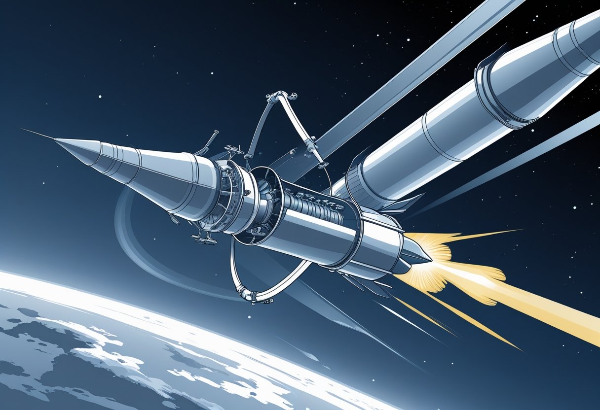
Key Components of a Rocket
Rockets combine high-energy fuel storage, controlled combustion and exhaust, precise navigation hardware, and a mission-specific payload to reach and operate in space. Each component must balance mass, strength, and reliability under extreme temperatures and pressures.
Propellant Tanks and Storage
Your rocket’s propellant tanks hold the fuel and oxidizer that supply the rocket engine with chemical energy. Tanks use lightweight, high-strength metals or composite materials and often include internal baffles to limit slosh that can shift the vehicle’s center of mass during ascent.
Cryogenic propellants (liquid hydrogen, liquid oxygen) require insulation, pressurization systems, and boil-off management; storable propellants (hydrazine, nitrogen tetroxide) trade handling ease for toxicity and lower performance.
Pressurization may use helium or autogenous pressurization from gaseous propellant to maintain feed pressure for pumps or to force propellant into the combustion chamber on pressure-fed systems.
You must consider structural margins, tare weight, and tank volume when sizing tanks because propellant mass dominates launch mass and mission performance.
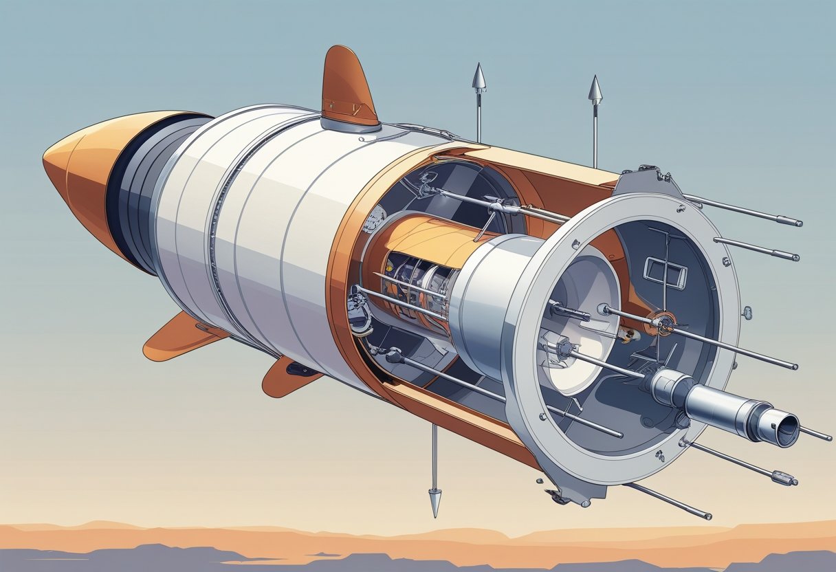
Combustion Chamber and Nozzle
The combustion chamber mixes and burns propellant to produce hot, high-pressure gas that the nozzle accelerates into thrust. Chamber design focuses on efficient mixing, stable combustion, and thermal protection—often using regenerative cooling where propellant circulates through chamber walls to absorb heat.
Nozzles convert high-pressure gas to high-velocity exhaust; nozzle shape and expansion ratio determine efficiency at different altitudes. A bell nozzle suits single-stage-to-orbit boosters; extendable or aerospike designs target better performance across wide ambient pressures.
Gimbaled engines pivot the nozzle to vector thrust and steer the vehicle during ascent. For smaller attitude adjustments or when main engines are shut down, reaction control systems (small thrusters) provide torque using pulses of propellant.
Combustion instability, cooling failure, or nozzle erosion are primary failure modes, so you’ll see redundancies and health-monitoring sensors in flight hardware.
Payload Section
The payload section houses the mission cargo—satellites, scientific instruments, cargo, or crew modules—and includes the structural adapters, fairings, and separation mechanisms. Fairings protect the payload from aerodynamic heating and acoustic loads during ascent; once above the dense atmosphere, fairings jettison to reduce mass.
Payload adapters provide mechanical attachment and electrical/thermal interfaces; separation systems use springs, pneumatic pushers, or pyrotechnics to ensure clean release without imparting unwanted spin.
For crewed missions, the payload area includes environmental control, life support mounting points, and abort interfaces. For satellites, you’ll find deployment systems like dispensers, separation rings, and precise timing systems to place the payload on the intended trajectory.
Mass, center of gravity, and mounting stiffness of the payload directly affect flight dynamics and guidance requirements.
Guidance and Control Systems
Your rocket’s guidance and control systems keep the vehicle on its planned trajectory using sensors, processors, and actuators. Inertial Measurement Units (IMUs) containing gyroscopes and accelerometers provide real-time attitude and acceleration data. Star trackers or GPS correct long-term drift for orbital insertion accuracy.
Flight computers run guidance algorithms and send commands to gimbaled engines, throttle settings, and reaction control systems. Reaction control thrusters handle fine attitude control, especially in vacuum where aerodynamic surfaces are ineffective.
Redundancy and fault-tolerant software protect mission-critical functions; cross-strapped sensors and multiple flight computers reduce single-point failures. You’ll also encounter telemetry links that stream health and state vectors to ground stations for monitoring and uplinked updates when needed.
Types of Rocket Engines
You’ll learn how engines differ by propellant and operating principle, which determines thrust, efficiency, and common uses like boosters, orbital insertion, or long-duration probes.
Chemical Rockets: Solid, Liquid, and Hybrid
Chemical rockets produce thrust by burning propellant and ejecting hot gases through a nozzle. Solid rockets use a pre-mixed solid propellant cast into a grain; they deliver high, immediate thrust and are simple and rugged. That makes solid rocket boosters good for first-stage liftoff, but they cannot be throttled, restarted, or easily shut down once ignited.
Liquid-fueled rockets store fuel and oxidizer separately and feed them into the combustion chamber. You can throttle, shut down, and restart many liquid engines; turbopumps or tank pressurization supply propellants. Liquid propellants (e.g., RP-1/LOX, liquid hydrogen/LOX) give higher performance flexibility and are common for core stages and upper stages.
Hybrid rockets mix a solid fuel grain with a liquid or gaseous oxidizer. They combine the safety and storability of solids with throttling and shutdown capability closer to liquids. Hybrids have simpler plumbing than liquids but lower performance, and are used in suborbital vehicles, experimental systems, and some small orbital launchers.
Key trade-offs:
- Thrust vs control: solids high thrust, low control.
- Complexity vs performance: liquids higher complexity, broader performance.
- Safety and cost: hybrids offer middle ground.
Electric and Ion Propulsion
Electric propulsion accelerates a propellant using electric fields, producing low thrust but very high efficiency (specific impulse). Ion thrusters ionize a noble gas like xenon, then use electrostatic grids or Hall-effect fields to accelerate ions to tens of km/s exhaust velocity. That yields far better propellant economy than chemical rockets but with thrust too low for launch from Earth.
You’ll find ion thrusters on deep-space probes and for station-keeping on satellites. They require substantial electrical power from solar arrays or nuclear sources, and they operate continuously for months or years to build up large ΔV. Typical uses include orbital transfers, long-duration attitude control, and cargo tugs in cislunar or interplanetary missions.
Practical considerations:
- Power source sizing (solar or reactor) limits thrust.
- Plume interactions and grid erosion set lifetime.
- Excellent for missions where time is flexible and propellant mass matters.
Nuclear and Alternative Propulsion Systems
Nuclear thermal propulsion (NTP) heats a low-mass propellant, usually hydrogen, in a reactor and expands it through a nozzle. That gives much higher exhaust velocity than chemical rockets while maintaining high thrust, making NTP attractive for crewed Mars transfers and high-ΔV maneuvers. Reactor materials, reactor temperature limits, and launch-safety constraints are the main engineering challenges.
Alternative concepts include nuclear electric propulsion (reactor + electric thrusters), which trades thrust for very high efficiency, and non-rocket options like solar sails that use photon pressure for propulsion without propellant. Solar sails offer near-zero propellant mass and very long mission lifetimes but produce extremely low acceleration, suitable only for slow, continuous trajectories.
Key points to weigh:
- NTP: high thrust, high specific impulse, complex reactor integration.
- Nuclear-electric: excellent efficiency, requires heavy reactors and radiators.
- Solar sails: no propellant, minimal acceleration, ideal for long-duration missions.
Fuel, Propellants, and Combustion
This section explains how stored chemicals create thrust, which combinations give the highest performance, and how engines stay cool under extreme heat. You’ll learn which propellant pairs carry their own oxygen, why liquid hydrogen and liquid oxygen are widely used, and how regenerative cooling protects engine nozzles.
How Fuel and Oxidizer Power Rockets
A rocket propellant always includes two roles: the fuel supplies chemical energy, and the oxidizer supplies oxygen for combustion. You carry both in rockets so combustion can occur in vacuum; common pairs are kerosene + liquid oxygen and liquid hydrogen + liquid oxygen. Combustion raises pressure and temperature in the chamber, then the nozzle converts that high-pressure gas into high-speed exhaust to produce thrust.
You should track three performance numbers: specific impulse (Isp), propellant density, and handling complexity. High Isp (e.g., LH2/LOX) gives efficient delta-v, but low density increases tank size. Dense fuels like RP-1 simplify tanks but give lower Isp. Choose propellants by mission needs: payload mass, launch infrastructure, and reusability constraints.
Key safety and operational differences matter. Storable hypergolic propellants ignite on contact and simplify ignition systems but increase toxicity. Cryogenic propellants require insulation and boil-off management. You must balance performance, logistics, and safety when selecting fuels and oxidizers.
Liquid Hydrogen and Liquid Oxygen
Liquid hydrogen (LH2) and liquid oxygen (LOX) form a high-performance propellant combination used for upper stages and main engines. LH2 offers very high specific impulse because its combustion products are light and exit the nozzle at very high velocity. LOX supplies the oxidizer in a compact, dense form relative to gaseous oxygen.
Temperature and density drive design decisions. LH2 stores at ~20 K and is extremely low density, so tanks grow large and insulation becomes a major mass penalty. LOX stores at ~90 K and is denser, which reduces tank volume but still requires cryogenic plumbing. You must manage boil-off and provide turbopumps that handle large mass flow rates and big density differences between LH2 and LOX.
Engine chambers and nozzles must accommodate a wide mixture ratio range; typical LH2/LOX engines run fuel-rich for cooling and to limit combustion temperatures. You’ll find LH2/LOX in vehicles where high delta-v and efficiency outweigh the penalties of large tanks and complex ground support.
Regenerative Cooling for Rocket Engines
Regenerative cooling routes cryogenic fuel through channels around the combustion chamber and nozzle before injection, absorbing heat and preventing material failure. This method uses the fuel as a heat sink, preheats it for better combustion, and eliminates the need for separate cooling loops. You’ll see it in most high-performance liquid engines.
Design trade-offs focus on channel geometry, wall thickness, and pressure drop. Narrow channels increase heat transfer but raise flow resistance; thicker walls improve strength but reduce cooling efficiency. Engineers use brazed channel liners, milled cooling jackets, or tube-wrapped nozzles depending on manufacturing limits and cycle type.
Regenerative cooling limits maximum chamber temperatures and extends engine life, but it requires careful thermal-structural analysis. If cooling flow drops or combustion runs hotter than predicted, hot spots can form rapidly. Proper instrumentation and redundant flow paths help you avoid catastrophic failures.
Staging and How Rockets Reach Orbit
Staging lets rockets shed dead weight and concentrate thrust where it matters most. You’ll learn why multiple stages increase payload, how the rocket equation limits design choices, and the role of escape velocity in leaving Earth.
Why Multistage Rockets Matter
You want the largest possible payload for a given launcher. Staging achieves that by discarding empty tanks, engines, and structure once they finish their job. A typical launch uses a heavy, high-thrust first stage to fight gravity and dense atmosphere, then lighter upper stages optimized for vacuum efficiency.
First stage operation focuses on high thrust-to-weight ratio and structural strength. Upper stages focus on high specific impulse (Isp) and precise burns to insert the payload into the intended orbit. Staging also reduces the mass you must accelerate, which improves delta-v performance and cuts required propellant dramatically.
Common staging patterns include two-stage and three-stage stacks; reusable first stages add recovery systems that slightly reduce payload but lower per-launch cost. You should note stage separation events are timed and controlled to avoid collisions and to ensure proper ignition of the next stage.
The Tyranny of the Rocket Equation
The Tsiolkovsky rocket equation governs how much delta-v you can get from a given mass and exhaust velocity: Δv = Ve ln(m0/mf). You need to manage the mass ratio (m0/mf) — initial mass versus final mass — to reach orbital speeds near 9.3–10 km/s including atmospheric and gravity losses.
Because ln(m0/mf) grows slowly, adding more propellant yields diminishing returns unless you also drop mass. That’s why staging is essential: each discarded stage resets the mass ratio calculation for the remaining vehicle, making further delta-v more efficient. Increasing engine exhaust velocity (higher Isp) helps, but practical chemical engines have limits.
In practical terms, you decide stage count, tank sizing, and engine type by trading structural mass, engine mass, and propellant mass. Staging converts otherwise impossible payloads into achievable missions by breaking the delta-v requirement into manageable steps.
Escape Velocity and Space Travel
Escape velocity from Earth’s surface is about 11.2 km/s, but reaching orbit typically requires less horizontal speed (orbital velocity ~7.8 km/s) plus vertical and loss penalties. You don’t always need full escape velocity to travel in space; reaching a stable orbit requires the correct combination of altitude and horizontal velocity.
If your mission targets interplanetary travel or leaving Earth entirely, the launcher or upper stage must add the additional delta-v beyond orbital injection. For example, a trans‑Earth injection burn from low Earth orbit may need a few km/s of extra delta-v depending on destination. The design of upper stages and interstage transfers therefore directly affects mission capability.
Practical flight profiles use gravity turn guidance to trade vertical lift for horizontal speed efficiently. Staging sequences and upper-stage engine restarts allow you to place payloads into precise orbits or to inject them on escape trajectories for deep-space missions.
Modern Rockets and Space Exploration
Modern rockets combine advanced propulsion, stage design, and mission planning to carry payloads from launch pads into orbit and beyond. You will see how reusability, iconic vehicles, major companies, and mission profiles shape current and near-term spaceflight.
Reusable Rockets and Next-Gen Technology
Reusability reduces cost per flight by recovering and refurbishing hardware instead of discarding it. You know SpaceX’s Falcon 9 first stage lands propulsively using grid fins and landing legs, enabling rapid turnaround and lower launch prices.
Reusable elements include boosters, payload fairings, and—planned—upper stages. Recovering stages requires extra mass for landing systems, so engineers balance reuse with payload performance.
Next-gen tech pushes that balance: methane-fueled engines like Raptor aim for higher performance and simpler reuse cycles than kerosene engines. Heat-resistant materials, autonomous guidance, and rapid-checkout ground systems shorten refurbishment time.
You should expect reusability to expand from low-Earth orbit launches to larger vehicles as thermal protection and inspection tech improve.
Famous Rockets: Saturn V, Falcon 9, Starship
Saturn V remains the benchmark for high-thrust, human-rated heavy lift. It delivered Apollo crews and hardware to translunar trajectories with three powerful stages and massive propellant capacity.
Falcon 9 transformed commercial access to orbit by proving routine first-stage recovery and high flight rates. Its Merlin engine cluster and graceful stage separation methods let you launch satellites, resupply the ISS, and fly crewed Dragon capsules.
Starship targets full reusability with a stainless-steel two-stage system: a Super Heavy booster and Starship upper stage. Its high-thrust Raptor engines use methane for deep-reuse and in-situ refueling concepts for Mars missions.
Each vehicle illustrates trade-offs: Saturn V prioritized payload mass; Falcon 9 emphasizes operational economy; Starship pursues scale and interplanetary capability.
NASA, SpaceX, Blue Origin, and Virgin Galactic
NASA funds and certifies major human and science missions while developing heavy-lift systems and deep-space technologies. You interact with NASA through programs, procurement, and standards when missions use government payloads or astronaut transport.
SpaceX leads commercial reusability and high-cadence launches. You can see its influence in lower launch costs and frequent rides to orbit for satellites and crew. Its Starship program also aims at lunar and Mars cargo and crew transport.
Blue Origin focuses on staged reusability and human tourism; New Shepard provides suborbital hops with vertical landing. New Glenn targets orbital heavy lift with partial reusability.
Virgin Galactic offers air-launched, winged suborbital flights for space tourism using a carrier aircraft and reusable spaceplane, emphasizing passenger experience and rapid flight cycles.
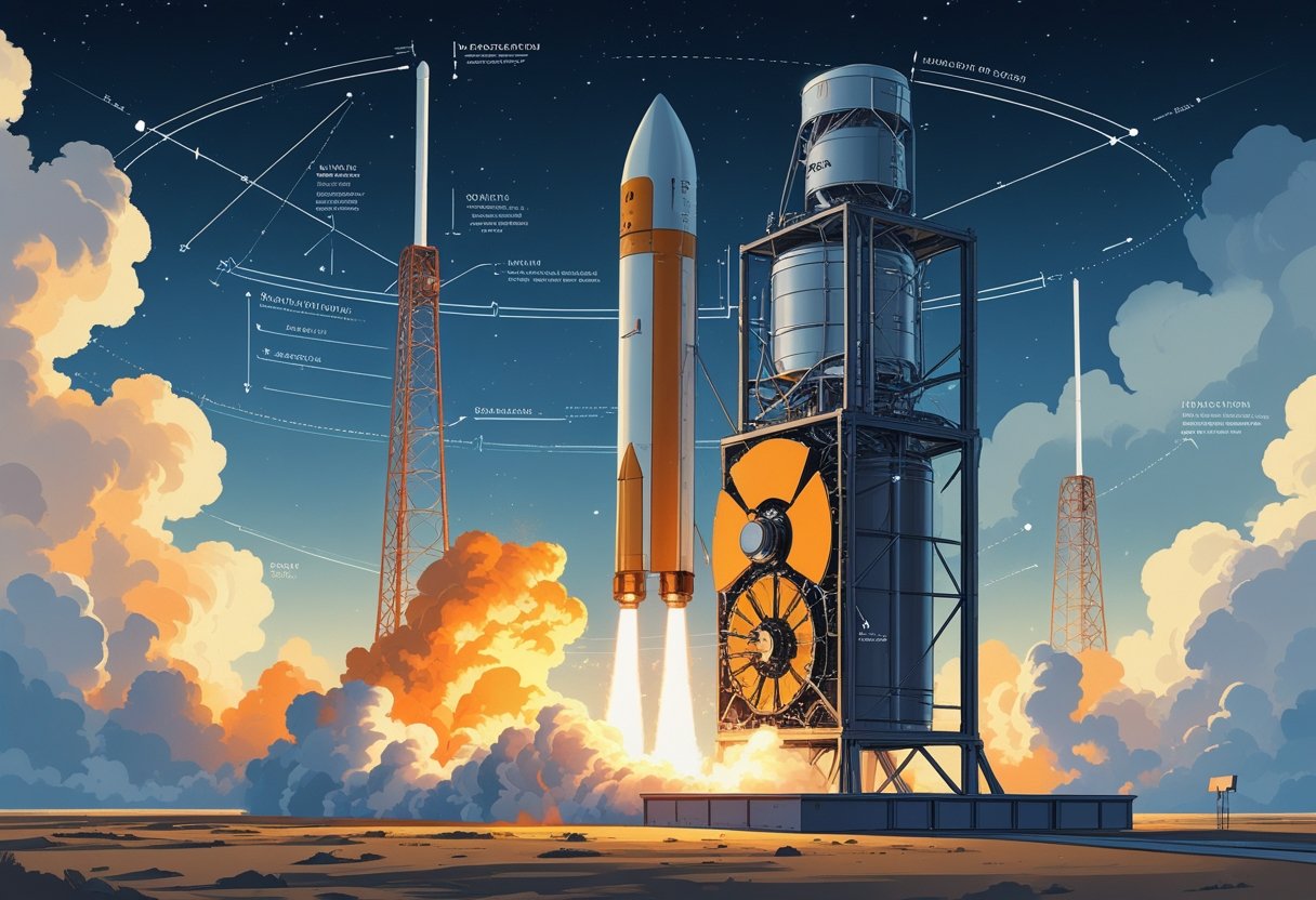
From Launch Pad to Deep Space Missions
At the pad, launch sequence steps include propellant loading, engine chill, guidance checks, and final hold release. You experience intense coordination between ground systems, range safety, and mission control during that countdown.
Ascent profiles optimize thrust and staging for orbital insertion; upper stages execute precise burns to place payloads into target orbits or on interplanetary trajectories. You rely on fairing separation and stage disposal plans to protect payload integrity.
For deep-space missions, spacecraft use upper-stage or transfer-stage propulsion, gravity assists, or in-space refueling to reach distant targets. You will see missions stage components differently: some expend upper stages, others plan on-orbit refueling or reusable tugs.
Modern exploration ties pad operations to long-term mission design, meaning what happens at liftoff directly affects your spacecraft’s ability to reach the Moon, Mars, or beyond.
A Brief History and the Future of Rockets
Rockets began as simple gunpowder devices and evolved into multi-stage vehicles that deliver satellites and humans to orbit. You’ll see how early military uses led to modern rocketry advances and which technologies will shape upcoming missions.
Early Rocketry to the Space Age
You can trace rockets back to medieval China, where gunpowder in bamboo tubes produced short-range “fire arrows.” By the 13th century the technology spread across Eurasia and shifted toward military applications, as described in detailed historical overviews like the one at Britannica.
In the 18th and 19th centuries, incremental improvements—metal casings and stabilizing fins—made battlefield rockets more effective. The 20th century changed everything: Tsiolkovsky, Goddard, and Oberth laid theoretical and experimental foundations for liquid-fueled and guided rockets.
World War II accelerated development with the German V-2, the first long-range guided ballistic missile. Postwar programs repurposed that expertise into orbital launchers, leading to Sputnik, crewed programs, and the Saturn V that enabled lunar landings. Short paragraphs like these help you follow the technical and historical steps without jargon.
Innovations in Rocket Science
You’ll encounter three major innovation threads: propulsion chemistry, staging and vehicle design, and guidance/control systems. Propulsion moved from black powder to liquid bipropellants (e.g., RP-1/LOX) and hypergolics, then to cryogenic hydrogen/oxygen for higher efficiency. That progression improved specific impulse and payload capacity.
Staging became essential: dropping empty tanks and engines reduces mass to reach orbit. Engineers refined separation mechanisms, interstage structures, and aerodynamic fairings to improve reliability. Guidance advanced from unguided trajectories to inertial and GPS-aided navigation, then to real-time flight computers and thrust vector control.
You should note reusable booster technology as a recent game-changer. Vertical landing and refurbishable first stages cut launch cost per kilogram and increased flight cadence. Contemporary reviews and educational resources like NASA’s teacher guides document these technical shifts in accessible detail.
The Road Ahead for Spaceflight
You will see near-term missions using heavy-lift rockets for lunar return and Mars precursors. Examples include government programs building super-heavy launchers and commercial vehicles designed for crewed lunar landings. Expect continued emphasis on payload mass to trans-lunar injection and on in-space propellant transfer demonstrations.
Longer term, you’ll watch developments in full reusability, high-thrust methane engines for simpler refurbishment, and advanced materials that lower structural mass. Emerging concepts—on-orbit refueling, integrated architectures for cargo and crew, and scaled manufacturing—aim to make sustained lunar presence and crewed Mars missions practical.
Key metrics to follow are launch cost per kilogram, turnaround time for reusable stages, and demonstrated in-space refueling; these will determine which companies and nations lead the next era of space exploration.
Leave a Reply