
Imagine you’re designing a bridge. Before spending millions of dollars building it, wouldn’t it be nice to know if it will hold up under heavy traffic? Or what happens during an earthquake? Or how it handles extreme temperatures?
This is exactly what Finite Element Analysis does. It’s like having a crystal ball for engineers—except instead of magic, it uses math and computers to predict how things will behave in the real world.
Sounds complicated? Don’t worry. By the end of this article, you’ll understand FEA well enough to impress your engineer friends at dinner parties. Let’s break it down together.
What Is Finite Element Analysis?
Finite Element Analysis, commonly called FEA, is a computer-based method that engineers use to predict how objects will react to real-world forces like heat, vibration, pressure, and other physical effects.
Here’s the key insight: Instead of trying to analyze an entire complex object at once (which would be nearly impossible), FEA breaks it down into thousands or even millions of tiny, simple pieces called elements. Each piece is small enough to analyze easily, and when you combine all the results, you get an accurate picture of the whole object.
Think of it like this: Imagine trying to understand how a mosaic painting looks from far away. You could study each tiny tile individually—its color, position, and how it connects to neighboring tiles. Put all that information together, and you understand the complete image. FEA works the same way, but with physical behavior instead of colors.
The Pizza Analogy: Understanding FEA in 30 Seconds
Let’s make this even simpler with a pizza analogy.
Imagine you have a whole pizza and you want to know exactly how hot every part of it is. Measuring the entire pizza at once is tricky. But what if you cut it into slices? Now you can measure each slice individually. Cut it into even smaller pieces, and your measurements become more precise.
FEA does exactly this with engineering problems. It slices up complex shapes into manageable pieces, analyzes each piece, and then combines everything to give you the complete answer.
The smaller and more numerous your pieces (elements), the more accurate your results. Of course, more pieces also means more computing power needed, so engineers must balance accuracy with practicality.
Why Does FEA Matter?
Before computers and FEA existed, engineers had two options for testing their designs: build physical prototypes and test them until they broke, or rely on simplified mathematical calculations that only worked for basic shapes.
Both approaches had serious problems. Physical testing was expensive, time-consuming, and sometimes dangerous. Mathematical calculations couldn’t handle complex real-world geometries.
FEA changed everything. Now engineers can test hundreds of design variations on a computer before building a single prototype. They can simulate extreme conditions that would be dangerous or impossible to recreate physically. They can find weak points in their designs and fix them before anyone gets hurt.
The impact is enormous. Products are safer, development is faster, costs are lower, and innovation happens at unprecedented speeds.
How Does Finite Element Analysis Work?
Let’s walk through the FEA process step by step. Don’t worry—we’ll keep the math out of it.
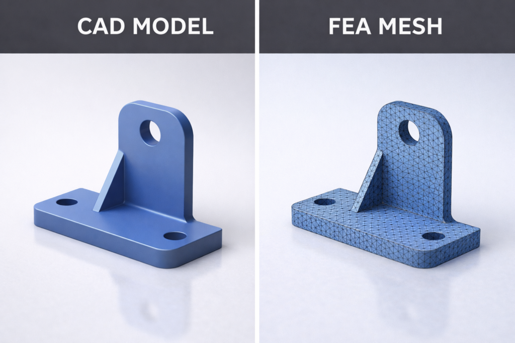
Step 1: Create the Geometry
First, you need a digital 3D model of whatever you want to analyze. This could be anything from a simple bracket to an entire airplane wing. Engineers typically create these models using CAD (Computer-Aided Design) software.
Step 2: Define Material Properties
The software needs to know what your object is made of. Steel behaves differently than aluminum. Rubber behaves differently than concrete. You input properties like stiffness, density, thermal conductivity, and strength.
Step 3: Generate the Mesh
This is where the “finite element” part comes in. The software divides your 3D model into thousands of small geometric shapes called elements. These are typically tetrahedra (like tiny pyramids) or hexahedra (like tiny bricks). The collection of all these elements is called a mesh.
Step 4: Apply Boundary Conditions
Now you tell the software how your object is constrained. Is it bolted to a wall? Sitting on a surface? Floating in space? These constraints are called boundary conditions, and they’re essential for getting realistic results.
Step 5: Apply Loads
What forces are acting on your object? This could be pressure, gravity, acceleration, temperature changes, or any combination of physical effects. You apply these loads to the appropriate locations on your model.
Step 6: Solve
Here’s where the computer earns its keep. The software sets up and solves enormous systems of mathematical equations—sometimes millions of equations simultaneously. This calculates how every single element in your mesh responds to the applied conditions.
Step 7: Analyze Results
Finally, you examine the results. The software displays colorful visualizations showing stress, displacement, temperature, or whatever you’re investigating. Engineers interpret these results to make design decisions.
Key Concepts You Should Know
Let’s cover some essential FEA terminology in plain language.
Mesh
The mesh is the collection of small elements that make up your model. Think of it as a net draped over your object, defining where calculations will happen. A finer mesh (more elements) gives more accurate results but takes longer to solve.
Nodes
Nodes are the corner points where elements connect to each other. They’re like the intersections in a road network. The software calculates values at these nodes and interpolates between them.
Elements
Elements are the individual building blocks of your mesh. Each element is a simple geometric shape with known mathematical behavior. Common types include triangles, quadrilaterals, tetrahedra, and hexahedra.
Degrees of Freedom
This describes how each node can move or respond. A node might be able to move in three directions (X, Y, Z) and rotate in three directions, giving it six degrees of freedom. Constraining degrees of freedom is how you apply boundary conditions.
Stress
Stress is the internal force per unit area within a material. High stress concentrations are often where failures begin, so engineers pay close attention to stress results.
Strain
Strain measures how much a material deforms under load. It’s closely related to stress—apply stress to a material, and it strains (deforms) in response.
Convergence
Convergence refers to how your results stabilize as you refine your mesh. If your answers change dramatically when you add more elements, your solution hasn’t converged yet. Engineers run convergence studies to ensure their results are reliable.
Types of FEA Analysis
FEA isn’t just one thing—it’s a family of analysis types for different engineering questions.
Structural Analysis
This is the most common type. It predicts how objects deform and where stresses develop under mechanical loads. Will this beam bend too much? Will this bracket break? Structural analysis answers these questions.
Thermal Analysis
Thermal analysis predicts how heat flows through objects and how temperatures distribute over time. It’s essential for electronics cooling, engine design, and building insulation.
Modal Analysis
Modal analysis finds the natural frequencies at which objects want to vibrate. This is critical for avoiding resonance—a phenomenon where vibrations amplify and can cause catastrophic failures.
Fluid-Structure Interaction
Some analyses combine fluid dynamics with structural mechanics. How does wind load affect a skyscraper? How does blood flow stress an artificial heart valve? These complex problems require coupled simulations.
Fatigue Analysis
Fatigue analysis predicts how long a component will last under repeated loading. A part might survive one heavy load easily but fail after a million light loads. This analysis is crucial for anything that experiences cyclic stress.
Real-World Applications of FEA
Finite Element Analysis touches almost every industry that designs physical products.
Aerospace
Aircraft manufacturers use FEA extensively to optimize every component for minimum weight and maximum strength. Every gram saved means fuel savings over the aircraft’s lifetime. FEA also simulates bird strikes, crash landings, and extreme flight conditions.
Automotive
Car companies simulate crashes, vibrations, thermal management, and durability long before building physical prototypes. FEA helps engineers design crumple zones that protect passengers and components that survive years of road abuse.
Civil Engineering
Bridges, buildings, dams, and tunnels are all analyzed using FEA. Engineers simulate earthquakes, wind loads, temperature changes, and long-term material behavior to ensure structures remain safe for decades.
Medical Devices
From artificial joints to surgical instruments to implantable devices, FEA helps medical engineers design products that work reliably inside the human body. It can even analyze bone and tissue behavior.
Consumer Products
Even everyday items benefit from FEA. Phone cases, furniture, sports equipment, and kitchen appliances are all optimized using simulation to balance strength, weight, cost, and aesthetics.
Energy
Wind turbines, nuclear reactors, oil platforms, and power plant components all undergo extensive FEA to ensure safe and efficient operation under demanding conditions.
Common FEA Software
Several software packages dominate the FEA landscape. Here are the most widely used options.
Commercial Software
ANSYS is perhaps the most comprehensive FEA package available, used across industries for every type of analysis imaginable.
Abaqus excels at nonlinear analysis and is particularly popular in academic research and advanced industrial applications.
NASTRAN has aerospace roots and remains a standard in that industry, known for its reliability and extensive validation history.
COMSOL Multiphysics specializes in coupled multi-physics problems where different physical phenomena interact.
SolidWorks Simulation integrates directly with SolidWorks CAD software, making it accessible for designers who want quick analysis capabilities.
Free and Open Source Options
CalculiX provides capable structural analysis without licensing costs and is popular in academic settings.
OpenFOAM focuses primarily on computational fluid dynamics but includes some structural capabilities.
FreeCAD with FEM Workbench offers integrated CAD and basic FEA for hobbyists and small projects.
Limitations of FEA
FEA is powerful, but it’s not perfect. Understanding its limitations makes you a smarter user.
Garbage In, Garbage Out
FEA results are only as good as your inputs. Wrong material properties, incorrect boundary conditions, or poor mesh quality will give you wrong answers that look completely believable. Always validate your assumptions.
Simplifications and Assumptions
Every FEA model involves simplifications. Real materials have defects and variations. Real loads fluctuate unpredictably. Real boundary conditions are never perfectly rigid or perfectly free. Engineers must understand what they’re simplifying and how it affects results.
Computing Resources
Complex models with fine meshes require significant computing power. Large simulations can take hours or days to solve, even on powerful workstations. There’s always a tradeoff between model fidelity and practical solve times.
User Expertise Required
FEA software will happily give you wrong answers if you set up the problem incorrectly. Interpreting results requires engineering judgment and experience. FEA is a tool that amplifies expertise—it doesn’t replace it.
Getting Started with FEA
Interested in learning FEA yourself? Here’s a practical path forward.
Build Foundation Knowledge
Start by understanding basic mechanics concepts: stress, strain, force, equilibrium, and material behavior. You don’t need advanced mathematics, but comfort with these fundamentals helps enormously.
Choose Beginner-Friendly Software
SolidWorks Simulation or Fusion 360 with Simulation are good starting points because they integrate with CAD and have relatively gentle learning curves. For free options, try FreeCAD or online tutorials with student versions of commercial software.
Follow Structured Tutorials
Most software vendors offer excellent tutorial content. Work through these systematically rather than jumping into complex projects immediately. Build skills progressively.
Start Simple
Begin with basic problems where you know the answer—a cantilever beam, a pressurized cylinder, a simple bracket. Compare your FEA results to hand calculations or textbook solutions. This builds confidence and catches setup mistakes.
Join Communities
Online forums, LinkedIn groups, and local engineering societies connect you with experienced practitioners who can answer questions and share insights.
Your Gateway to Virtual Prototyping
Finite Element Analysis represents one of the most powerful tools in modern engineering. It transforms complex physical problems into manageable computations, enabling engineers to explore designs virtually before committing to physical production.
Understanding FEA basics opens doors to deeper engineering knowledge and practical career skills. Whether you’re an aspiring engineer, a curious hobbyist, or a professional looking to expand your toolkit, FEA knowledge pays dividends.
The concepts aren’t as intimidating as they first appear. Break complex objects into simple pieces, apply the laws of physics to each piece, combine the results, and you have FEA in a nutshell.
Now that you understand the basics, perhaps it’s time to download some software and try it yourself. The best way to learn is by doing, and there’s never been an easier time to start exploring the world of simulation.
Leave a Reply